Wednesday, October 7, 2009

Introduction to Ethernet

Hey Folks!

Based on my lesson today I'll be giving my notes on a basic introduction to Ethernet.

I'll be covering:

1. The evolution of Ethernet
2. CSMA/CD - The Essence of Ethernet technology
3. Methods of Communicating in the LAN
4. The official explanation of a MAC address

Here is a short background on what we know as Ethernet:

1973: Xerox invents Ethernet (3 Mbps)
1982: Ethernet standardized between vendors (10 Mbps)
1995: Fast Ethernet emerges (100 Mbps)
2000: Gigabit Ethernet emerges (1000 Mbps)
2002: 10 Gigabit Ethernet emerges (10000 Mbps)
2007: 100 Gigabit Ethernet emerges (100000 Mbps)

How about a short review on common storage terms we face everyday?

1 Byte = 1 character (For you C programmers out there, its like char temp = 'C')
1024 Bytes = 1 Kilobyte
1024 Kilobytes = 1 Megabyte
1024 Megabytes = 1 Gigabyte
1024 Gigabytes = 1 Terabyte

and so forth....

However when we talked about the Ethernet speeds as mentioned earlier, we used Mbps.... Mbps here stands for mega bits per second.

You may ask....well then why did you just give us that that explanation using Bytes?

Byte vs bit? What's the difference?

All you need to know is that 1 byte is equal to 8 bits. Furthermore all of you probably know that a bit is just a representation of 1 or 0.

Therefore:

1 Byte = 8 bits
1024 Bytes = 1 Kilobyte = (1024 * 8 = 8192) bits

and so forth....

So remember when work with networks, we think of BITS not BYTES!!!

-----

With relation to the OSI model, Ethernet maps to the bottom two layers. That means it is both a data link and physical entity.

On the data link layer, it is further sub-divided into the Logical Link Control Layer (LLC) and the Media Access Control Layer (MAC).


Now don't worry about the sub-division here, as its very logical.

The MAC layer is what we are accustomed to so far, that is the MAC addresses we have been using so far when we speak over layer 2.

Now the LLC layer is a bit new to us at the moment. This layer allows us to choose which direction we are going to be going into the network layer. Let us expound on this...

The network layer, as we know it so far, uses IP addresses to communicate. However you can have other types of network layer communication. Some of these include IPSX, Apple-talk and others. The LLC field allows us to choose IP on the network layer when we are using TCP/IP to communicate.

Therefore when a packet arrives to a machine and its moving from the bottom to the top of the OSI model, the LLC portion of the data link layer will decide whether or not to send the packet to IP or some other addressing mechanism.

With regards to the physical standards, Ethernet specifies several types of communication. These include cat 5 cables, wireless, fiber optics, etc...These are the different venues of communication that Ethernet supports.

-----

Now let us discuss the CSMA/CD which are the set of rules governing how you talk on an Ethernet network. After all, just like a real life meeting at work, there are rules on how you speak to such a network.

Every part of the network, such as PC, switch, even the layer 2 portion of the router, have to be able to correctly interact with an Ethernet network.

Let's go over them, shall we?

The rules are called the CSMA/CD standard. The acronym CSMA/CD stands for:
  • Carrier: The network signal. This just means that there is going to be signals sent on Ethernet.

  • Sense: The ability for all the members of a network to determine whether or not there is a Carrier signal at a given time. The real life equivalent is to imagine yourself in a meeting at work. You must be able to 'sense' that someone is talking and therefore wait for them to finish before you can say anything.

  • Multiple Access: All devices have equal access. There is no favoritism here! Just gotta wait till its quiet on the network before you can say anything out loud.

  • Collision: What happens if two devices send at once? Two people 'sensed' that it was safe to send out something on the network at the same moment in time.

  • Detection: How the computers will handle collisions when they happen.

-----

Now let's move onto the methods of communicatino that can take place on Ethernet. This is fairly straightforwad, so you can relax a bit.....Not that today's session has been difficult.

Anyway, let's begin with term known as Unicast. Here is a visual on what take place during a unicast message:


Here, the computer marked with 172.16.1.11 can use a switch to directly send a packet over to 172.16.1.10. This should be straightforward.

Now the Broadcast form of communication just means that the packet will go to every destination on the network (excluding the one who sent it). It's just the opposite of unicast.

A good example of a broadcast message is the ARP protocol we were discussing earlier. An ARP request is sent to everyone on the network, so that the member with the matching IP address can reply with their MAC address.

Here is a visual:


Notice here that the packet sent out by 172.16.1.11 is sent out to the switch as a broadcast message. The switch will then in turn flood all its ports with that message to all other members on that network. However it is important to note that the switch will NOT send this packet out back to the originating machine.

The last type of communication we'll cover is Multicast. Think of it as a 'special people's club' message. Its meant only for a subset of people on the network.


As you can see that as the host machine sends the multicast message out onto the switch, the data only goes to 2 out of the 3 other network members.

Different applications use different forms of communication for different purposes.

-----

Lastly, let us discuss the official explanation of the MAC address. We've used them a lot, but we havent' gone into the gritty details.

We discussed the octets and the different classes of IP addresses, but now is where we will go into the construction of the MAC address.


First, its important to note that the MAC address has 12 characters. That is how long they are.

Furthermore MAC address characters are each hexadecimal. This means they have the range of 0-9 or A-F.

The left most 24 bits of the MAC address are known as the "Organizational Unique Identifier" or the OUI.

Since each hex character needs 4 bits to represent itself, that means that the first 6 characters of the MAC address (24 bits) represent this.

The OUI is part of a range of addresses that manufacturers register for in order to use for their devices.

For example in the image above, this vendor is allowed to use 00:19:D1 as OUI portion of the MAC address for all network devices they manufacturer.

Some OUI addresses are well known and you can see what manufacturer is responsible for making your network card by plugging in your network card's MAC address at

http://www.coffer.com/mac_find/

The second half of the MAC address is left up to the manufacturer to assign for their devices.

And that's it for today....short and sweet.

Tuesday, October 6, 2009

Basic TCP/IP: The Tale of Two Packets

Today I'll be going over a story called the "Tale of Two Packets" which was given by the teacher of the CCNA series I am following.

The goal is to walk through a scenario as two packets named "Bob" and "Sally" make their way through the network.

This is going to be more of a review then anything else.


Let's begin with the short story of Bob.

-----

Bob is going to represent local communication. That means he will only traverse within the confines of his local network. In our example below, he's moving from the top computer to the one right below it. Notice they are within the same network (subnet).

Assume that the subnet mask for Bob's network is 255.255.255.0.

Bob doesn't seem very adventurous does he....


Now let's assume that Bob represents a 'ping' packet. That means that someone opened up a command prompt or UNIX shell on the computer marked as 172.10.1.20 and decided to run:

ping 172.10.1.30

Now based on what you learned from the earlier lessons, what exactly will happen here?

1. The local machine will compare the IP address of the destination (172.10.1.30) with the subnet mask of the local network.

2. Now how exactly will the comparison work? If you answered: "The comparison works by comparing the first 3 octets of the destination IP address with the first 3 octets of our IP address"....then you answered correctly. Remember that since the subnet mask is 255.255.255.0, that we are going to be comparing the first 3 octets only. The last octet will represent the host.

3. In our case, the top computer will realize "Hey this guy is on the same network as me! I don't have to go through any router to reach him. So coooool".

4. What will the top computer have to do next? He'll have to figure out the MAC address of the computer below. Remember he has to have the destination MAC address to reach the other end. Now do you remember how we resolve an IP address to a MAC address? We use the ARP protocol.

5. I am sure you are bright enough to remember that ARP works by broadcasting a request out on the local network for the IP address its trying to resolve. So in our case, the top computer will just yell out loud to everyone on the local network: "Hey Guys! Who is 172.10.1.30? Whoever you are, could you please get back to me with your MAC address? Thanks!!!"

6. Now since this is a broadcast everyone on the local network will get the request....that includes the router that is connected to this network. He'll get the request and say "Hmm well this ARP request is for 172.10.1.30 and not for me. I guess I'll just drop this ARP request packet".

7. Now the computer below will receive the ARP request and he'll reply back to the top computer and he'll say "Hey Buddy! I am the guy you're looking for. My MAC address is AA00:BC33:3211".

8. Next, our host computer will say "This is good, very good. I now have the layer 2 destination MAC address to speak to you with!"

9. Finally our host computer will create a packet (Bob) who has a source IP of 172.10.1.20 and a destination IP of 172.10.1.30 and has a source MAC address of 342F:39BC:3923 and a destination MAC address of AA00:BC33:3211. The packet will be sent out on our local network and our switch fill forward it along to the destination computer.

That's pretty straightforward....now the fun stuff....

-----

Let's move onto the story of Sally. She's a bit of a complicated and adventurous woman....

Here is the preliminary setup:


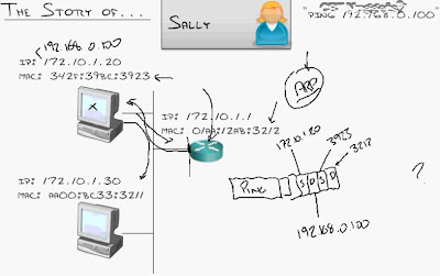
Sally is also going to be a ping packet. However, unlike Bob, she'll be going from the top computer on the left side (172.10.1.20) over to a remote server at 192.168.0.100. Obviously you can see that these two boxes are on totally different networks (subnets) with several routers separating them.

I sense some serious router traversal about to take place....

Let's begin by zooming in on the network of the local machine which will send out the packet. We need to take care of some stuff before we can start bouncing around through the routers.


As mentioned before, someone begins Sally's life by opening up a command prompt or a Unix shell on the computer marked as 172.10.1.20 and running:

ping 192.168.0.100

Now based on what you learned from the earlier lessons, what exactly will happen here?

1. Well just as in the case of Bob our local machine will compare the network portion of the IP address of our destination with the network portion of our IP address. Based on the subnet for this network (255.255.255.0), the network portion of the IP address represents the first 3 octets.

2. The host machine will clearly see that 192.168.0.x does NOT mach 172.10.1.x.....what to do? The destination IP address is not on the same network as the sender....Sally is such a complicated woman.

3. Clearly now we can't just yell out and use the ARP request....Sally's destination is not on the same network as us. Remember that the ARP request is a broadcast for locally connected machines. An ARP request does not go past a router and our destination here lies past the router. I hope you remember our discussion on how the router's number one job is to stop broadcasts from leaving the local network....

4. Our local machine now realizes it has to send Sally out through the local router (it's default gateway). So it creates the Sally ping packet and throws on the source IP address (172.10.1.20), the destination IP address (192.168.0.100) and.......wait.....what do we put for the source and destination MAC addresses?

5. The answer is quite interesting. For the source MAC address we put our own MAC address: 342F:39BC:3923. But what about the destination MAC address?

6. To find the destination MAC address of the router we have to communicate with router just as it was another device within the network. Think of how Bob's story went. Remember that Bob had to communicate with a local member of the network. Well the router is also a local member of the network. So therefore we send a ARP request to find out the MAC address of our default gateway (172.10.1.1).

7. Our local machine will yell out: "Hey guys, who on the local network here is 172.10.1.1? I need your MAC address please!!". The router will respond with its MAC address to the calling machine.

8. The result of the router's reply is going to be our destination MAC address. Therefore before we send Sally out, we assign the destination MAC address to be 01AA:12AB:3212.

Let's take a break and look at an updated image:


You'll notice that the Sally ping packet now has the source and destination IP addresses explained above and the source MAC address of the host machine (ending in 3923) and the destination MAC address of the router (ending in 3212).

Let's move on....

9. The router will pick up the packet and observe that it is indeed for the router because the destination MAC address matches that of the router.

10. Then the router will open up the network portion of the packet and notice that the destination IP address does NOT match the router's IP address. The router feels sad and says "Gosh no one ever wants to directly talk to me. This is another case where someone wants to use me to get to another network. It's okay though, I'll help him out".

Since the router from our originating network has Sally at the current moment, let's take another short break and move into the the zoom of the router portion of Sally's story......


Notice that the blue arrow represents the router that Sally is currently at.

Moving on....

11. The router now thinks to itself: "Well I am not directly plugged into a network which would contain 192.168.0.100. However, my magical routing table has informed me that in such scenarios I should send all unknown traffic over to 10.10.1.2. He is the man that can bail me out and send Sally to the correct destination".

12. Next, the router will strip off the layer 2 MAC addresses in the Sally packet before sending Sally out. The router will however NOT touch the layer 3 IP addresses in said packet. Remember, the source and destination IP addresses are not to be changed! Only the MAC addresses will be changed as Sally swims from one router to another.

13. Well so what will go in the source and destination MAC address in Sally's packet? Well the source MAC address will be the MAC address shown for the interface of the router where the IP address is 10.10.1.1. This is because Sally will be sent out from this interface on the router. The destination MAC address in Sally's packet will be the MAC address of the interface represented at 10.10.1.2.

Here is a little bit of visualization:


Notice the arrows pointing to the source and destination MAC addresses as Sally traverses the 10.10.1.x network.

Also note that a router has a separate interface with a different IP configured for each network its connected to.

Moving on...

14. Now after replacing the MAC addresses, router A (as shown in the image above), will push Sally over to router B.

15. Router B now has Sally in his possession and he's thinking to himself: "Well this packet is not destined for me, since I am not 192.168.0.100. However I do have a routing table which has instructed me on what to do in such situations".

An updated image with the router details of where we are in Sally's progression through the network:


16. Just as the router before did, the new router that owns Sally will also push Sally along to the next hop router as specified in the routing table. Therefore you should be able to figure out that the source MAC address for Sally will be 35BB:1290:18FF and the destination MAC address will be 3222:AAAA:FFB1. Remember the source and destination IP addresses are not affected inside the Sally packet.

17. Saving you the trouble of repeating the steps above with the last router shown on the far right, let's move onto what happens as Sally approaches her destination:


18. Finally Sally has arrived at the last router she will have to go through. This router (shown as router D in the image above) says "Oh this is so neat. Looks like the destination IP address that Sally is destined for is in one of the networks I am connected to!".

19. Router D will then strip off the source and destination MAC addresses that allowed Sally to reach from router C to router D and replace them with some new information.

20. This new information will be a little tricky to obtain. Remember now that router D knows that the destination machine for which Sally is meant for lies on the network the router is connected to. However, just as every router has done before, router D will have to strip off the source and destination MAC address. The source MAC address is fairly straightforward; it's just going to be AF30:BC33:3211. What will the destination MAC address be?

21. Before the router can assign the destination MAC address for Sally's final stop, the router must issue an ARP request here to find out what it is. Remember that the router can't use its routing table to send Sally over to the destination as the routing table is just for speaking to other routers. Therefore router D will yell out loud "Who is 192.168.0.100? Please respond to me with your MAC address please!! Thanks!!".

22. The server shown in the image will respond to the ARP request and tell the router "Hey Mr. Router D, I am indeed the guy you're looking for. My MAC address is 88A8:12AF:0399

23. Lastly router D will now assign its destination MAC address to what the server replied with and send Sally out to her final resting place. Remember that this entire time the source and destination IP addresses haven't been touched.

The reverse of this whole process will also happen as the remote web server has to respond to the Sally ping request. Of course due to brevity, we won't go into the details.

As a general note whenever router to router communication takes place, we use the routing tables to figure out where to go next. Whenever local communication takes place within a specified network (think of Bob from earlier) we use ARP to resolve the destination.

This is very important knowledge and its imperative you understand it. Without this knowledge you'll have trouble has try to troubleshoot networks in the future.

If you get some time, play around with the "traceroute" command on Unix or the "tracert" command on Windows. It will show you every hop it takes for your packet to reach a specified destination.

Here is the wikipedia on traceroute: http://en.wikipedia.org/wiki/Traceroute

You have now become Layer 2/3 experts!! Well not really....

Monday, October 5, 2009

Basic TCP/IP: Understanding Port Numbers

Today we'll go over the other half of the Transport layer communication: Port Numbers.

We'll cover in this session:

1. How port numbers work.
2. The well known port numbers.

Should be a fairly short session....Let's get started!

Remember, everytime an application communicates across the network , not only does it have to choose a protocol of communication (TCP vs UDP), but it has to generate a port number.

Specifically it has to generate a source port and a destination port. Fairly straightforward so far I hope...

How about story time now? You know how much I love stories...

-----

Let's re-visit our example from earlier.


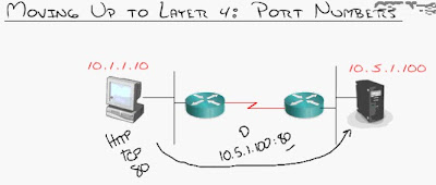
We have our machine on the left side (10.1.1.10) who is trying to access the web server on teh right side (10.5.1.100). You've seen this scenario multiple times by now.

Well when our machine tries to browse the web we use the famous Layer 7 protocol HTTP. Well HTTP is well known for using TCP. How would your web pages look if they weren't displayed in a reliable manner? Your html and images would look all mangled....that's why HTTP always uses TCP....well 99% of the time HTTP uses TCP....

In any event, HTTP also uses the well known port number 80. This port number is reserved for HTTP to do its thing. So when we send a packet to the web server we use the destination port as port 80. You can see the image for more details.

This way the remote server knows that since the packet we sent is meant for port 80, that the packet's ultimate destination is the web server process (Apache for example).

For a list of the well known port numbers, visit:
http://www.iana.org/assignments/port-numbers

Some of the famous port numbers are:
FTP which is at port 21
SSH which is at port 22
HTTP which is at port 80
World of Warcraft which is at port 3724 (Yes it's famous!)

-----

Now what about the source port number? We discussed the destination port number that we assign when we send out a packet, what about what do we put in the source port number field?

Well you just have to think in 'inverse' terms and it will make sense. Just as the web server is a server that is handling requests, our local machine also behaves as a 'server' of sorts and handles requests as well.

We may be browsing the web, using Skype, have World of Warcraft running....all sorts of things. Just check your taskbar (if you're a Windows user) and you'll see all sorts of apps sitting there (and clogging your memory most likely).

So the point then becomes, how does incoming traffic into our machine know which app to reach? If my World of Warcraft character picks up an item and that packet is sent back to our machine, how does it know to enter my World of Warcraft session as opposed to my web browser? That's where the source port number comes into play. Souce port numbers are generated so that return traffic can be handled accordingly.

For example, when our local machine visits a web site, we'll send port 80 as the destination port number....however for the source port number we'll generate a dynamic new port number so that the web server knows how to respond to us.

Here is an example on Windows. Let's say we visited a few websites recently....


Here you'll see the output of "netstat -f" which you can run on any Windows machine. It will give you all the recent port number activity taking place on your machine.

You can see that we recently visited ebay which is shown in the image above towards the bottom. You'll also see that instead of listing 80, the output has shown "http" here. This is because with "netstat -f", the port numbers as well as the IP addresses of your destinations are resolved to their English equivlanet.

If you had run "netstat -n" the output would have not resolved the English equivalents:


On *nix machines you can also run netstat for similar detail. Make sure to run "man netstat" to see its usage.

Now if you look on the columns labeled "Local Address" you'll see our IP address followed by a dynamically generated source port number. In the examples above most of them seem to be in the 52000 range.

Therefore when we send data out, we put these dynamically generated numbers as our source port numbers. So when the web server, for example, wants to respond to us, they know what to put in their destination port number.....Something in the 52000 range in our example.

That's how we can do so many things through the inter-webz at once!

-----

Now let's revisit some of the super popular well known port numbers. These are like the popular people in high school; such as the starting QB for your high school, the arrogant cheerleader squad and the Prom queen.

You can probably tell I didn't hang out with them in high school....


Notice towards the bottom right of the image that 0-1023 are the well known reserved port numbers. This means that these are super uber special guys. What do I mean by that?

Well it means that if you want to write an application (perhaps a new online PC game) that uses TCP/UDP over the internet, you can't use any of the first 1023 port numbers. You'd have to use a port number beyond that range.

Now you'll notice that both TCP and UDP each have 65535 port numbers. These are different and mutually exclusive port numbers.

For example, port 65 on TCP and port 65 in UDP may both be used for totally different things. In the image above you'll see that port 53 refers to the DNS server in TCP but the DNS client on UDP.

However there are cases where they may be used for similar functionality as well. A common example of where they are used for similar functionality is HTTP, where both TCP and UDP use port 80.

For individual details on FTP, SSH, Telnet, SMTP, TFTP, DNS Client, etc.. its best to refer to their respective Wikipedia pages.

In general TCP applications are much more common.

That's it for today!

See its not too bad....

Sunday, October 4, 2009

Basic TCP/IP: TCP and UDP Communication

In today's exciting session, we'll go over:

1. Understanding the difference between TCP and UDP
2. The TCP three way handshake
3. TCP sequence numbers and acknowledgments
4. TCP Windowing

Let's review a bit, shall we?

Make sure you remember that a network always communicates in layers.

At the bottom, the physical layer is where the electric signals and the 1's and 0's move along.

Then you have the data link layer where the MAC addresses allow you to communicate on the local network. Local network implies you and your buddies are all connected to the same switch...you haven't gone through a router.

The IP address on the network layer allows us to communicate end to end, no matter where we are located in the world or how many routers we have to go through....these addresses stay the same throughout their travels.

Now as we move up from physical to data link to network, you'll see that today's discussion will be about the Transport layer (TCP vs UDP).


Remember that the choice between TCP and UDP is the choice between reliable and unreliable communication. You can see the high level differences in the image above.

If you remember from our earlier discussion, that UDP is great for video and audio, where you don't really need 100% of every single packet to arrive at the destination.

TCP is what is used most of the time such as when we browse the web, check email use a FTP server, etc...

Now if you notice you'll see that TCP builds a connection and UDP is connectionless. This is pretty self-explanatory for now.

The next question is, how does TCP guarantee reliable delivery? Well it uses a nifty trick called 'sequence numbers'. How does this trick work? Well its fairly simple...

Each packet that is sent out by TCP will have a sequence number inside the TCP header. For example, a series of packets going out from your local machine to a web server may have the sequence numbers 1,2,3,4....10 on the first 10 packets that you send to the web server. This way, the remote side (the web server) knows how to re-assemble the data even if the packets arrive out of order.

What if your packets don't reach the destination at all? How will re-assembly take place? Well TCP uses whats called 'acks' which is short for 'acknowledgments' for each individual packet that it sends. Unless TCP gets an ack for each and every packet it sends to the destination, it will continue to retransmit until the acks arrive.

Now we can move onto some more specifics.

Let's begin with UDP, which is fairly simple. We just simply send out a packet with the source and destination IP addresses marked in the packet. That's it....we don't do anything else.

Think of it this way.....You want into a room and say out loud "I want to hand John this letter!" and then you simply throw the letter to him and walk out. You don't even know if John was in the room....you don't know if he got it or not.....that's UDP. You hope for the best but prepare for the worst.

TCP, however, is a bit complicated. It will actually start a conversation (session) with the device its trying to communicate. They way it begins this conversation or session is by using what's called the 'TCP Three Way Handshake'. Let's go into how it works....

The three way handshake begins by the source machine sending out a 'syn' packet to the destination machine it wants to communicate with. Now here 'syn' is short for syncrhonization, meaning that we want to syncrhonize with the destination.

The destination will respond with a packet that says 'syn-ack'. The 'syn-ack' comes from the fact that the destination is now saying "Not only do I want to synchronize with you but I want you to know that I am acknowledging your syn packet".

Now remember everything in TCP is reliable, so the source will send back an 'ack' packet to acknowledge the 'syn-ack' that was sent by the destination. Now we're good to go.

Every time you open a browser and visit some website, you are doing the above.

----

Now that the three way handshake is completed, your computer will begin either sending or receiving data with the destination its communicating with...in our case a web server.

As mentioned before TCP will use sequence numbers to verify reliable delivery, so let's take some time to go through an example to see how all this fits together.


Let's say our computer decides to send a packet to the web server and marks the packet with sequence number 10. In reality these numbers are much larger, but we are just using a small number here for easier understanding.

Anyway the receiver will catch the packet sent by our machine and respond by saying "Okay cool, now I have a stream of data that I want to send you. Therefore I'll start sending data to you and I'll begin with sequence number 5".

You may be asking, where are these numbers coming from? Well these numbers have some complex background where they come from and how they are maintained, but for now, we don't have to worry about it.

In any event, if you see the image that relates to our example above you'll see not only is the web server sending us a packet with sequence number 5, but its also sending an 'ack 11'. This means that the web server has acknowledged the packet with sequence number 10 that we sent over to him and he's waiting for a packet with sequence number 11.

Now the source machine will receive this from the web server and he'll say "Oh cool, he got my earlier packet. Now I'll send him a new packet with some more data I want to send him and I'll stamp that with sequence number 11. Not only this, I'll let the web server know that I got the packet that he was trying to send by 'ack'-ing sequence number 6".

Note that the packet we send to the web server contains not only our new data with sequence number 11 but it also contains the ack for 6 (which is the sequence number the destination is sending on).

If only real life worked so smoothly...

Now as we move along the destination will say "Oh so cool, you got my packet 5 from earlier, so I'll send you some new data with sequence number 6. Oh and by the way, I got your packet 11 earlier so I'll ack for 12 now".

This is how it goes back and forth....each side has a sequence number they are sending on while the other side acknowledges.

-----

Now let's say something goes wrong....horribly horribly wrong....

Let's say the message that we sent earlier from our machine to the web server gets dropped. The packet I am referring to is the one that had the sequence number 11 and the ack for 6.


Well TCP uses timers here to retransmit just in case packets don't arrive as they should. Therefore in our example the web server will create a timer and wait for a message back from the host machine which has the 'ack 6'. If it doesn't get the ack back from our host machine within a specified time interval, it will re-send its packet to the host machine with its data and sequence number 5 along with the ack 11.

Our host machine will notice this and say "Hey why is the web server re-sending the same stuff from earlier? He must have not got my packet....I guess I'll re-send it again".

So the host machine will resend its packet (sequence number 11 and ack 6).

Its pretty simple to understand. The web server will keep re-sending its data along with the sequence number its working on along with the ack needed for the host machine. It will re-send this packet over and over until the correct response comes back from our host machine.

-----

Let's move up a notch now...since you are so advanced....

If you think about what we have so far, its not very efficient. We send a packet and wait for an acknowledgment. We do this over and over again. This can get very laggy....

To resolve this there is a concept known as TCP Windowing. The idea is to send bursts of traffic based on how reliable the connection is. Here's the idea:


We begin by sending one packet and then we get the acknowledgment. Okay, this is cool, let's step it up a bit.

This time we send two packets full of data and receive an acknowledgment back. This is pretty cool, let's step it up further!

Then we move onto four packets and so forth. This will actually continue to increase without limit until a problem is detected. A problem occurs when you overwhelm the other side. So we keep on increasing the amount we send until the other side says "enough!".

How will the other side say "enough is enough!"? Well the other side will acknowledge and say "Look buddy, I only partially received what you were trying to send....could you slow it down a bit?". In our example you'll see that the 'X' marks the packets the remote side failed to acknowledge.

At this point the host machine will reduce how much it sends each time. However later on, the host machine will try again to bump it up a bit.

-----

How about an example?

Here is the diagram for our example. Assume that the three way handshake has already taken place.


  • We begin by sending out a packet with sequence number 1 to the web server.
  • The web server acks 2 saying that it now expects a packet with sequence number 2 next. All is well in the world at the moment.
  • Now we get a bit aggressive so we send out two packets with sequence numbers 2 and 3.
  • The web server steps it up a notch as well and acks for 4 meaning that it got the packets with 2 and 3 and is now ready for a packet with sequence number 4.
  • Now we get even more aggressive and send out four packets with sequence numbers 4, 5, 6 and 7.
  • The web server has finally met its match and could not handle our flurry of packets. Hence it acks 7 back to us. This means that the web server received 4, 5, and 6 but could not get 7....since it has ack'ed 7. If it had gotten 7 he would have acked back 8.
  • We understand the limits imposed by the web server so we now know we can send a maximum of three packets at a time.
  • Now for the next wave of packets, we send the three packets with sequence numbers 7,8 and 9. We have to re-send 7 because our web server didn't get it earlier.
So now you understand TCP Windowing. Its a pretty cool concept that lets TCP gradually increase and hit the limits for sending traffic.

That's all for today. Remember to try to memorize the different ranges for the 3 different IP address classes!

Saturday, October 3, 2009

TCP/IP Addressing Fundamentals

Today I'll cover the following:

1. How does the OSI Model and TCP/IP relate?
2. Understanding the two address concepts
3. IP address format
4. Default IP Address classes
5. Public vs Private addresses

Let us begin with the model of TCP/IP...its most commonly referred to the 'Department of Defense model'.....If you find out why that is, please let me know....

The first three layers of the OSI model that we discussed earlier map to the application layer in the TCP/IP model. As for the the other layers, they are fairly straightforward in their conversion.....see the image below.


Actually back in the day, the OSI model used to compete with the TCP/IP model...but the TCP/IP model won out in the end in terms of usage; however the OSI model is what is still used to describe network communication.

Let's move into to some more TCP/IP details....

First thing to remember is that TCP/IP is not just one protocol...its a team!

Take a car manufacturer for example. There are plants that make the parts, there are assembly lines, there are delivery trucks, there are sales lots and then there are maintenance shops....its a giant team!

Just like that TCP/IP is a suite of protocols....see below:

We have application layer protocols such as Telnet, FTP, SMTP and then we have transport layer protocols such as TCP and UDP.

However today we will focus on the IP part of TCP/IP....that's our main goal for today.

Lets begin by trying to understand what an IP address consists of:

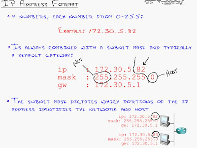
I'm sure you know by now, but each IP address consists of 4 numbers. Each number can range from 0-255. Some people call each of these 4 numbers an octet....so hence there are 4 octets in an IP address.

This gives us many possible combinations for IP addresses but we are still running low in the world today!! That's the reason for IPv6....but that's much later on.

In any event, an IP address is always combined with a subnet mask and typically a default gateway. We'll come back later to the default gateway which is labeled as 'gw' in the image above.

Now the subnet mask represents which portions of the IP address represent the 'network' and which represent the 'host'. Are you confused yet?

A good way to understand the subnet mask is to tell yourself that whenever you see 255 anywhere in the subnet mask, that represents the network and wherever you see a 0 in the subnet mask, that represents the host.

Simple isn't it?

In the example above, the network at the bottom has two machines on its local network. You'll see that their first 3 octets are the same....172.30.5.x. This means they are on the same network.

The benefit for this is that its much easier for them to speak as they are right next door to each other! There is no router needed for them to speak. Think of it as your family members in your home....you can just yell out loud and your sibling in the room over can hear you.

Now as mentioned earlier, the last octet will determine which part of your IP address is the host. In our example in the image above we have two hosts: 82 and 83.

How is any of this helpful? Why do I need to know this?

Well the goal is to try to break up your network into smaller networks as networks get larger and larger. This is because a large network will eventually reach a point where if you have too many members connected, there will be too much chatter and no one would be able to communicate.

If you grew up in a house with lots of family members, I'm sure you'll understand. When you have 10 or so brothers or sisters and everyone is yelling at once in the house, it makes it hard for anyone to understand anything.

This touches on the concept of the broadcast domain which we will come across later.

Now let us re-emphasize the usefulness of the two address concept; that is the IP address and the Ethernet MAC address....let's work on a little story together.

Here is how the story goes....I'll show an image towards the end of the story to visualize everything a bit.

  • We are giong to be using a subnet mask of 255.255.255.0 for all the networks in our story. Yes we are going to have multiple networks, but don't be scared!
  • This will mean that the first 3 octets will represent the network and the last octet will represent the host on that network You'll notice in the image below that we have a different network across each router. That's because (you guessed it) routers are a layer 3 device which represent different networks.
  • In the story we are telling, we have a Cisco router in our home which has the IP address of 10.1.1.1.
  • You want to share a file from 10.1.1.10 to 10.1.1.11. Let us assume you want to share a file called file.zip
  • So the local machine you're on asks itself: "Is the machine I want to send the file to on the same network as me??"....and indeed since the first 3 octets match on 10.1.1.10 and 10.1.1.11, the two machines are indeed on the same network.
  • Now what? What do we do now? Take a breather for now.....
  • Well we found out that guy we want to send the file to is really just our neighbor. So what would you do in real life if you wanted to tell your neighbor something? How would you tell your sibling in your house something? That's right....you'd yell out loud! That yelling protocol is known as ARP or the Address Resolution Protocol.
  • Now how does ARP work? Well ask yourself how yelling works. When you yell out loud, no one else can talk while you're yelling....and your loud voice can (usually) reach everyone.
  • What happens next? We'll since your yelling out loud and looking for host 11....(think of calling out your brother's name in the house because you're looking for him).....host 11 will eventually hear your yell and will respond back by saying "Ooo that's me!" and it will respond to you by giving you its MAC address.
  • Now we have a direct line to host 11. So so so cooooool...........
  • It may seem kind of odd.....why do we need to do this? We have the IP of the destination, so why do we go through this yelling business to find the MAC address? Well its because computers can't speak using IP, they can only speak using a MAC address.....that is layer 2 addresses.
  • Now obviously there is a source and destination IP address in the packet, but layer 2 is where the transfer of information actually occurs.
  • Layer 2 will then use layer 1 to psychically carry of your file.zip to your destination.

Now lets move onto a different story, this time we'll generate a bit of a twist....

What if you need to speak to a host on a different network? Let's say your on 10.1.1.10 and you want to speak to your file server located on another network at 10.5.5.100? Just as before you want to send file.zip over.....Here is what happens:
  • Your local machine will say: "Hey I want to copy a file over to 10.5.5.100"
  • Just as before your local machine will check to see if the destination is on the same network as itself. It will be sad to find out that 10.5.5.x does not match 10.1.1.x.....what now?
  • We can't yell anymore......meaning we can't use the ARP protocol from earlier. Remember that only worked if the destination was on your local network, which its not in this case.
  • What happened if you tried to yell? Well in simple terms, the router would just prevent your voice from reaching any other network...that's the router's main job. It's go to prevent the broadcast domain from stretching from one network to another. Hence the wisdom of using routers to reduce your network....so that the yelling domain (broadcast domain) can be reduced.
  • Now since you can't yell past the router, we simply have be to be nice and hand off our request to the router (our default gateway). He is the main man who can propagate our yelling request to the outside world in a nice manner.
  • Our default gateway (router) is located at 10.1.1.1. This is the 'default' place to go if you don't know how to find the MAC address of your destination. How does our local machine know what the default gateway's IP address is beforehand? Simple, its configured!
  • As we said before all network devices must have a MAC address, so even our router has a MAC address. Now we can use the yelling process (ARP request) to find out the MAC address of our router. This is just like the process we used to find the MAC address of the destination in our previous story when it existed our same network.
  • The router will respond back and say: "Hey that's me! Here is my MAC address. You can forward all your traffic for different networks through me!!!"
  • So how will our packet look like now? The source IP will be 10.1.1.10 and the destination IP will be 10.5.5.100. What will our MAC addresses be? The source MAC address will be our local burned MAC address and the destination MAC address will be the router's MAC address.
  • So now as the packet is sent out to router. The router will then open up the packet to inspect it and it will see "Hey this MAC address is for me, that's so cool, I feel so flattered". However this flattery will not last long when the router sees that the destination IP address is not the IP address for the router. Remember the IP address for the router is different then the destination IP address mentioned in the packet.
  • The router then says "Awww shucks, he's just using me to try to reach someone else. It's okay though I'll help him out. Lots of people use me to reach someone else"
  • Next, the router will say "I want to help this brother out, but I am not plugged into the 10.5.5.x network. I'm only plugged into the 10.1.1.x network and the 10.2.2.x network. However I have a plan...."
  • You may ask what secret plan does the router have....let's read on....
  • The router says "Well I want to help this guy out, and though I can't directly reach this network, I have a buddy of mine who told me he can reach this network. Therefore I'll forward this packet to him. He's over at 10.2.2.2"
  • Before the router sends the packet over to 10.2.2.2, he will strip off the layer 2 source and destination MAC addresses and replace them with different MAC addresses.
  • The source MAC address will be of the interface located at 10.2.2.1 and the destination MAC address will be of the interface located at 10.2.2.2.
  • This process will repeat itself until you reach the network of where your destination IP address resides. At this point the source MAC address will be from the router interface that plugs into the destination's network and the destination MAC address will be your destination's physical MAC address.
Here is a image with the some garbled details from the story I was referring to:


-----

Story time is over for now...lets move into some IP addressing basics.

There are three different default address classes:

Class A:
- First octet of IP address is 1-126
- Example is 10.5.1.1
- Has subnet mask 255.0.0.0
- Leads to 16,777,214 hosts on your network (not a good idea...Cisco recommends not to exceed 500 hosts per network because then the broadcast chatter reaches too high)

Class B:
- First octet of IP address is 128-191
- Example is 150.51.233.1
- Has the subnet mask 255.255.0.0
- Leads to around 65,536 hosts per network...still high

Class C:
- First octet of ip address is 192-223
- Example is 220.1.50.63
- Has the subnet mask 255.255.255.0
- Gives you aruond 254 hosts per network
- Most common type

If you look at an IP address you can tell what class your IP address is by default....just run ipconfig (in Windows) and look at the first octet:


Here we have a Class B address followed by a couple of Class C addresses. The 172 in the first one makes it a Class B address and the 192 in the subsequent addresses make them Class C addresses.

If you can, try to memorize the octet ranges, its very helpful later on.

-----

Its been a long post so let's move into the last thing for today.

Public vs Private addresses:


Public addresses are usable on the internet as they allow the world to be able to see you. How do you get one? Typically they are acquired from a service provider (Spring, AT&T, etc...)

Service providers typically buy blocks of IP addresses from the government.

Private addresses are usable only on internal networks. Their ranges are shown above.

If you are in an organization, 99% of the time you will be assigned a private address.

This begs the question, if everyone has a private address, how does anyone at work surf the web? Believe me, people have to surf the web at work....how will we make it through otherwise?

This is where a concept called NAT comes into the picture. It allows several people to 'share' a public IP address.

The most obvious example is your home. Think of the small Linksys or Dlink box you have that connects your house to your high speed connection.

All the devices in your house use a private IP address (usually along the lines of 192.168.1.x). However when you send traffic out of your house, the router will auto-magically hide your private IP address and make it seem as though you are communicating using your public IP address.

Up to several thousand people can shared a single public IP address....

Last few notes here from the image above:

The Loop back range is used for testing and its range is 127.x.x.x.....don't worry about this for now.

The Auto-configuration range is 169.254.x.x....don't worry about this for now either....it's just a call for help so that the machine using this address can be assigned an IP address....

That's all for now, and I apologize for the long posts. However there is always detail involved so I am trying my best to make it fun!

Tune in next time.....

Friday, October 2, 2009

The OSI model

You may be thinking..."Ahh gosh who needs to know the OSI Model? Its so simple! Its just seven little layers that I memorize using some sort of odd phrase such as 'Please do not throw sausage pizza away' or something similar"

The answer is simple...you need to know the foundation...even if it means re-learning something so trivial.

Remember small steps and eventually everything will become clear and you will obtain the most in depth of details.

So let us begin....

The model is as follows:

7. Application
6. Presentation
5. Session
4. Transport
3. Network
2. Data Link
1. Physical

And as I mentioned above, some commons ways to memorize the layers is using phrases such as "Please do not throw sausage pizza away" or "All people seem to need data processing". You'll likely never actually need to know or memorize these, unless you come across someone who has a lot of free time and happens to ask you for some odd reason or another.

Now one may say "Gosh this is very simple, I can memorize this, but why are you spending time on this?".

The answer is pretty simple:
1. The OSI model helps 'break down' network functions. Think of the foundation of a house. You can't build much of the house without setting up the foundation.
2. The OSI model creates a standard for equipment manufacturing....This way we can buy Cisco, Nortel and Juniper equipment and still have a functioning network.
3. The OSI model allows vendors to focus in on specialized areas of the networks.

I hope you're not bored yet....and if you are, take a breather and realize your motivations again. Remember you must 'Love Thy Network'!

Continuing onto the details of the OSI model....Let us go layer by layer starting from the top:

1. Application layer:
  • This layer interfaces with the application itself....Forgive the fairly obvious comment :)
  • This layer is able to provide network access to the application....think web browser, email, World of Warcraft, etc...
2. Presentation Layer:
  • "Generi-fies" the data that is to be presented to the layer above....Think of HTML, JPEG, etc...
  • This layer also provides Generic Encryption Services. This is useful, for example, when a client and webserver want to know how to speak
  • In general this layer is used to make data generic, compliant and standard
3. Session Layer:
  • Starts and ends sessions......Forgive me for the obvious again
  • Also logically keeps sessions separate
  • Issues requests to the layer below (Well isn't that a bit obvious?)

THIS IS WHERE I DRAW THE LINE....Why do you ask do I draw the line here? It's because the layers above (for all practical purposes) are not that important. In terms of pure networking knowledge the layers above all take place within the confines of a single machine....we're trying to re-aaquire our networking knowledge....so don't worry too much about what's above....lets move onto the important stuff....

4. Transport Layer:
  • I can't begin to tell you how important this layer is. This point alone is important enough to earn its own bullet point.
  • It really is that important....I'll give it another bullet point.
  • This layer dictates 'how' the data is sent....this is a high level description
  • It is at this layer we define well known services which run on ports. For example, how can a server know that incoming traffic is for its local web server as opposed to its local email server?
  • The decision of reliable vs un-reliable traffic is also decided here. Real time apps such as Voice over IP or Video usually use unreliable transport (who care's if you see a missing pixel here and there?) while everything else uses reliable transport. More details later....
5. Network Layer:
  • Provides "logical" addressing....this is where IP addresses are assigned
  • The Network layer has the job of finding the best/shortest path to the destination
6. Data Link Layer:
  • Provides "physical" addressing....we'll get into "physical" vs "logical" in more detail later on
  • Ensures that data is error-free
7. Physical layer:
  • Provides access to the cable
  • Electrical signals and one's and zero's go out here....
  • You don't need to worry 'too much' about this layer

Visuals always help so lets give you a before and after picture....here is the before:


Now lets go into some detail....about what happens when you use the internet!

Remember we are going from the top down on the left and then bottom up on the right. Also, it goes without saying, that as the packet goes from top to bottom on the left side it adds headers and information as it goes down the model. By the time we get to the bottom, everyone has added their 2 cents worth of information. What a democratic system indeed!

  • Let us assume there is a client on the left side (perhaps your pc) and they want to access cisco.com. We will assume for the moment that our IP address is 10.1.1.5.
  • The first thing that happens is that our request goes to a local DNS server, which translates cisco.com into an IP address....more on this later....just remember computers understand IP and not words like we do....that's why we need the IP address as opposed to the letters
  • DNS comes back and tells us that cisco.com is at 200.1.1.1...This is great news as we know how to reach the webserver that is hosting cisco.com!
  • So now we go down the OSI model....the Application layer requests a web page
  • The Presentation layer packages a request into an HTTP request, it then passes it down to the Session layer
  • The Session layer creates its own 'session'...we might have other things going on....online radio, itunes, etc...
  • Now we are in the most important layer....here we decide between reliable vs un-reliable or TCP(reliable) vs UDP(unreliable). In our example since we are using a web browser, we will choose to use the reliable TCP at this layer.....This will require an acknowledgment from the opposing side....more details on this later....
Now for some good stuff...just making sure you're still paying attention!
  • The session layer will team up with the transport layer to assign source and destination ports....why may you ask? Well the destination port number is necessary so that our message ends up at the correction location when it reaches its destination!
  • Wouldn't it be odd if you had to visit a friend in an apartment building but you didn't know his apartment number inside the building? That would be most odd indeed!
  • Since we are trying to communicate with the web server in our example here, the well known port number 80 is chosen here for HTTP traffic going to a web server.
  • Now the million dollar question....what is the source port number here? The answer is that it is dynamically assigned. Why do we need a source port number to begin with? So the webserver knows who to respond to when it comes back! Otherwise how will it know to send the homepage of cisco.com back to your specific web browser window? In our case here the source port number is 1098.
You're still there I hope! Insert snazzy comment here to keep you interested! Now, what happens next?
  • Moving onto the network layer....Here is where we will assign the source and destination IP address. In our example we have the source as 10.1.1.5 and the destination as 200.1.1.1. As a 'general' rule the IP addresses will never change as the packet progresses through the internet.
  • Now we come to the data link layer, where the source and destination mac addresses are added onto the packet.....You may now be asking "Why do we need both the source and destination mac addresses?"....Patience grasshopper, and all will come to you....
  • The source mac address is easy....if you don't know by now the mac address is the hard coded hex string that is burned onto your network card....so your machine will simply copy that value into the source mac address....In our example our mac address is 00-A0-15-11-B9-F2.
  • The destination mac address is a little tough....In our example we don't know the hard coded hex string that is burned onto the network card of the web server that is hosting cisco.com....so we simply add the mac address of our default gateway (our local router) and have him figure out the rest....way more detail on this later....For now, the mac address of our default gateway is 00-B9-11-11-22-22.
Many people ask....Why do we need an IP address AND a mac address....well the IP address is for end to end communication....think of it as a phone number to call your buddy....

The mac address is for local communication....think of it has the extension you may call (x4567) if you were in your office and wanted to speak to your neighboring cube.

One is for local and the other is for the end to end picture.

Here is the final picture.....with all the numbers mentioned above...


Welcome to the only networking guide you'll ever need

Hey folks,

In my continuous effort to try to spend some of my free time wisely I've begun this little blog to assist myself and others to pick up all those networking basics that we may have forgotten oh so long ago.

Questions such as "How does TCP/IP handle network congestion?" or "What the heck does a default gateway mean?" are sometimes posed by seasoned programmers.

Why do you ask?

Why is it that a seasoned programmers forget such concepts even if they work in the networking domain? Simple...they just never need to know/care about it.

I came from such a background and now I find myself starving for all those fundamentals that I knew a while ago but simply have forgotten.

In any event, I will post on this blog my daily notes and pictures from my quest to obtain my CCNA. You will find the details of my notes with explanation of all the concepts needed to get your switching/routing/tcp/ip knowledge back to what it was before.

There are always details in life, no matter where you go. What makes my blog so special is that it will work with you step by step giving you the foundation before moving forward.

If you try to learn the networking fundamentals online, you'll notice a plethora of information that is far and wide and highly sparse. If you want to start from the foundation and move up in small intervals until you reach a good amount of detail, this blog is where you need to be.

So get on board and bookmark my blog. You'll see updates as I progress with my studies, so be sure to take advantage of all my notes and explanations.

If you have questions, post a comment on a blog entry and hopefully you'll find yourself with a correct answer to your inquiry.

Followers